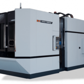
ORION horizontal machining centers are designed and manufactured to deliver excellent machine precision with the use of high precision components and thermo-friendly features.
ORION is a prominent constellation of bright stars located on the celestial equator and visible throughout the world. ORION series is a constellation of next-gen horizontal machining centers setting new benchmarks in specifications and performance for our global clients. It is a result of Indo-German engineering excellence for your competitive manufacturing.
Orion Series 1
| ORION SERIES 1 | |||||||
| AXES | ORION H 4000 | ORION H 5500 | |||||
| Traverse (X/Y/Z) | mm | 600 × 560 × 600 | 800 × 800 × 800 | ||||
| Rapid Rates(X/Y/Z) | m/min | 60 | 60 | ||||
| Max acceleration | g | 0.9 | 0.7 | ||||
| Table top to spindle center | mm | 100-660 | 100-900 | ||||
| Table center to spindle face | mm | 100-700 | 100-900 | ||||
| SPINDLE- std | ORION H 4000 | ORION H 5500 | |||||
| Spindle taper | type | HSK A 63 | HSK A 63/ BT 40 | ||||
| Spindle power, Fanuc, Cont./S2 | kW | 18.5 / 22 | 18.5 / 22 | ||||
| Maximum spindle torque, Cont./S3 | Nm | 50 / 120 | 50 / 120 | ||||
| Spindle power, Siemens Cont. | kW | 26.4 | 26.4 | ||||
| Maximum spindle torque, S1/S6 25% | Nm | 126 / 84 | 126 / 84 | ||||
| Spindle speed- Fanuc (Siemens) | rpm | 12,000 (15,000) | 12,000 (15,000) | ||||
| Spindle acceleration time - Fanuc (Siemens) | sec | 0.7 (2.5) | 0.7 (2.5) | ||||
| Spindle bearing diameter | mm | 70 | 70 | ||||
SPINDLE - HIGH TORQUE OPTION - Fanuc/ Mitsubishi | ORION H 4000 | ORION H 5500 | |||||
| Spindle power- cont./S2 | kW | - | 22/26 | ||||
| Maximum spindle torque- cont/S3 | Nm | - | 136/302 | ||||
| Spindle speed | rpm | - | 14,000 | ||||
| Spindle bearing diameter | mm | - | 80 | ||||
SPINDLE - HIGH TORQUE OPTION - Siemens | ORION H 4000 | ORION H 5500 | |||||
| Spindle power- cont | kW | - | 26 | ||||
| Maximum spindle torque- cont/S6, 25% | Nm | - | 150/230 | ||||
| Spindle speed | rpm | - | 14,000 | ||||
| Spindle bearing diameter | mm | - | 80 | ||||
| INDEX TABLE | ORION H 4000 | ORION H 5500 | |||||
| Pallet size | mm | 400 × 400 | 500 × 500 | ||||
| Pallet type | tapped holes | tapped holes | |||||
| Load capacity | kg | 400 | 700 | ||||
| Maximum job swing(dia × height) | mm | 630 × 750 | 800 × 1000 | ||||
| Pallet height from ground level | mm | 1100 | 1100 | ||||
| Index positions | deg | 360 × 1deg | 360 × 1deg | ||||
| Direct drive rotary table - optional | deg | 360,000 × 0.001 deg | 360,000 × 0.001 deg | ||||
AUTOMATIC TOOL CHANGER | ORION H 4000 | ORION H 5500 | |||||
| Number of tools | No | 40(60) | 40(60) | ||||
| Max tool diameter with adjacent pockets, full/empty | mm | 75/125 | 80/165 | ||||
| Maximum tool length | mm | 360 | 430 | ||||
| Maximum tool weight | kg | 8( 40T) / 12(60 T) | 8( 40T) / 12(60 T) | ||||
| Tool changing time- BT/HSK- retaining collet | sec | 1.0(3kg tool weight) | 2.0(1.4)(3kg tool weight) | ||||
| Chip to chip time(min)As per ISO 10791-9 | sec | 2.4(3kg tool weight) | 3.7(3.1)(3kg tool weight) | ||||
PALLET CHANGER | ORION H 4000 | ORION H 5500 | |||||
| Pallet change time(avg load,excluding seat check time) | sec | 9 | 9 | ||||
ACCURACY AS PER ISO 230/2 | |||||||
| Linear Axes | ORION H 4000 | ORION H 5500 | |||||
| Positioning A- with encoder (with linear scale option1) | mm | 0.010(0.008) | 0.010(0.008) | ||||
| Positioning R- with encoder (with linear scale option1) | mm | 0.007(0.005) | 0.008(0.005) | ||||
| ROTARY AXES | |||||||
| Positioning A | arc sec | 10 | 10 | ||||
| Repeatability R | arc sec | 7 | 7 | ||||
MACHINE INSTALLATION DATA | ORION H 4000 | ORION H 5500 | |||||
| Basic weight | kg | 10,000 | 12,000 | ||||
| Floor space (machine only) W*D | mm | 2550*4525 | 2775*5283 | ||||
| Compressed Air | bar | 6 | 6 | ||||
| Total Connected load- Cont/30min | kVA | 40/50 | 50/60 | ||||
| Power Supply | 3 phase, 415 V, 50 Hz | 3 phase, 415 V, 50 Hz | |||||
CNC SYSTEM: Fnuc Oi MF+/Mitsubishi | |||||||
| ORION SERIES 2 | |||||||
| AXES | ORION H 5500-50 | ORION H 6600 | ORION H 8000 | ORION H 8800 | |||
| Traverse (X/Y/Z) | mm | 740 × 740 × 800 | 1000 × 1000 × 1000 | 1250 × 1000 × 1000 | 1400 × 1200 × 1350 | ||
| Rapid Rates(X/Y/Z) | m/min | 60 | 60 | 60 | 40 | ||
| Max acceleration | g | 0.7 | 0.6 | 0.6 | 0.4 | ||
| Table top to spindle center | mm | 120-860 | 120-1120 | 120-1120 | 155-1355 | ||
| Table center to spindle face | mm | 20-820 | 150-1150 | 200-1200 | 200-1550 | ||
| SPINDLE- std | |||||||
| Spindle taper | type | HSK A 100/ BT 50 | HSK A 100/ BT 50 | HSK A 100/ BT 50 | HSK A 100/ BT 50 | ||
| Spindle power, Fanuc, Cont./S2 | kW | 22/ 30 | 30/37 | 30/37 | 30/37 | ||
| Maximum spindle torque, Cont./S3 | Nm | 249/ 414 | 353/699 | 353/699 | 353/699 | ||
| Spindle power, Siemens Cont. | kW | - | - | 63/63 | 63/63 | ||
| Maximum spindle torque, S1/S6 25% | Nm | 126/ 84 | 300 | 300 | 300 | ||
| Spindle speed- Fanuc (Siemens) | rpm | 10,000 | 10,000 | 10,000 | 10,000 | ||
| Spindle acceleration time - Fanuc (Siemens) | sec | 3 | 3 | 3 | 3 | ||
| Spindle bearing diameter | mm | 90 | 100 | 100 | 100 | ||
| SPINDLE - HIGH TORQUE OPTION - Fanuc/ Mitsubishi | |||||||
| Spindle power- cont./S2 | kW | - | 30/37 | 30/37 | 30/37 | ||
| Maximum spindle torque- cont/S3 | Nm | - | 505/1009 | 505/1009 | 505/1009 | ||
| Spindle speed | rpm | - | 6,000 | 6,000 | 6,000 | ||
| Spindle bearing diameter | mm | - | 120 | 120 | 120 | ||
| SPINDLE - HIGH TORQUE OPTION - Siemens | |||||||
| Spindle power- cont | kW | - | 37 | 37 | 37 | ||
| Maximum spindle torque- cont/S6, 25% | Nm | - | 585/885 | 585/885 | 585/885 | ||
| Spindle speed | rpm | - | 6,000 | 6,000 | 6,000 | ||
| Spindle bearing diameter | mm | - | 120 | 120 | 120 | ||
| INDEX TABLE | |||||||
| Pallet size | mm | 500 × 500 | 630 × 630 | 800 × 800 | 800 × 800 | ||
| Pallet type | tapped holes | tapped holes | tapped holes | tapped holes | |||
| Load capacity | kg | 700 | 1250 | 1500 | 2000 | ||
| Maximum job swing(dia × height) | mm | 800 × 1000 | 1050 × 1300 | 1250 × 1300 | 1450 × 1450 | ||
| Pallet height from ground level | mm | 1100 | 1250 | 1250 | 1250 | ||
| Index positions | deg | 360 × 1deg | 360 × 1deg | 360 × 1deg | 360 × 1deg | ||
| Direct drive rotary table - optional | deg | 360,000 × 0.001 deg | 360,000 × 0.001 deg | 360,000 × 0.001 deg | 360,000 × 0.001 deg | ||
| AUTOMATIC TOOL CHANGER | |||||||
| Number of tools | No | 40(60) | 60(80/120) | 60(80/120) | 60(80/120) | ||
| Max tool diameter with adjacent pockets, full/empty | mm | 125/250 | 125/250(315 with limit) | 125/250(315 with limit) | 125/250(315 with limit) | ||
| Maximum tool length | mm | 500(410 for BT 50) | 600 | 600 | 600 | ||
| Maximum tool weight | kg | 20(40 T) 25 (60T) | 30 | 30 | 30 | ||
| Tool changing time- BT/HSK- retaining collet | sec | 2.9(2.0)(7kg tool weight) | 2.9(2.0)(7kg tool weight) | 2.9(2.0)(7kg tool weight) | 2.9(7kg tool weight) | ||
| Chip to chip time(min)As per ISO 10791-9 | sec | 4.7(3.8)(7kg tool weight) | 5.1(4.2)(7kg tool weight) | 5.3(4.4)(7kg tool weight) | 6.1(7kg tool weight) | ||
| PALLET CHANGER | |||||||
| Pallet change time(avg load,excluding seat check time) | sec | 9 | 14 | 16 | 25 | ||
| ACCURACY AS PER ISO 230/2 | |||||||
| Linear Axes | |||||||
| Positioning A- with encoder (with linear scale option1) | mm | 0.010(0.008) | 0.010(0.008) | 0.010(0.008) | 0.010(0.008) | ||
| Positioning R- with encoder (with linear scale option1) | mm | 0.008(0.005) | 0.008(0.005) | 0.008(0.005) | 0.008(0.005) | ||
| ROTARY AXES | |||||||
| Positioning A | arc sec | 10 | 10 | 10 | 12 | ||
| Repeatability R | arc sec | 7 | 7 | 7 | 9 | ||
| MACHINE INSTALLATION DATA | |||||||
| Basic weight | kg | 13,000 | 20,000 | 22,000 | 26,000 | ||
| Floor space (machine only) W*D | mm | 3100*5300 | 3465*6222 | 3765*6472 | 3965*7150 | ||
| Compressed Air | bar | 6 | 6 | 6 | 6 | ||
| Total Connected load- Cont/30min | kVA | 50/60 | 80/90 | 80/90 | 80/90 | ||
| Power Supply | 3 phase, 415 V, 50 Hz | 3 phase, 415 V, 50 Hz | 3 phase, 415 V, 50 Hz | 3 phase, 415 V, 50 Hz | |||
| CNC SYSTEM: Fnuc Oi MF+/Mitsubishi | |||||||
| ORION SERIES 3 | |||||||
| AXES | ORION H 10000 | ORION H 12000 | |||||
| Traverse (X/Y/Z) | mm | 1600 × 1400 × 1400 | 2000 × 1400 × 1400 | ||||
| Rapid Rates(X/Y/Z) | m/min | 40 | 40 | ||||
| Max acceleration | g | 0.4 | 0.4 | ||||
| Table top to spindle center | mm | 120 -1520 | 120-1520 | ||||
| Table center to spindle face | mm | 300 - 1700 | 300-1700 | ||||
| SPINDLE- std | |||||||
| Spindle taper | type | HSK A 100/ BT 50 | HSK A 100/ BT 50 | ||||
| Spindle power, Fanuc, Cont./S2 | kW | 30/37 | 30/37 | ||||
| Maximum spindle torque, Cont./S3 | Nm | 353/699 | 353/699 | ||||
| Spindle power, Siemens Cont. | kW | 63/63 | 63/63 | ||||
| Maximum spindle torque, S1/S6 25% | Nm | 300 | 300 | ||||
| Spindle speed- Fanuc (Siemens) | rpm | 10,000 | 10,000 | ||||
| Spindle acceleration time - Fanuc (Siemens) | sec | 3 | 3 | ||||
| Spindle bearing diameter | mm | 100 | 100 | ||||
| SPINDLE - HIGH TORQUE OPTION - Fanuc/ Mitsubishi | |||||||
| Spindle power- cont./S2 | kW | 30/37 | 30/37 | ||||
| Maximum spindle torque- cont/S3 | Nm | 505/1009 | 505/1009 | ||||
| Spindle speed | rpm | 6,000 | 6,000 | ||||
| Spindle bearing diameter | mm | 120 | 120 | ||||
| SPINDLE - HIGH TORQUE OPTION - Siemens | |||||||
| Spindle power- cont | kW | 37 | 37 | ||||
| Maximum spindle torque- cont/S6, 25% | Nm | 585/885 | 585/885 | ||||
| Spindle speed | rpm | 6,000 | 6,000 | ||||
| Spindle bearing diameter | mm | 120 | 120 | ||||
| INDEX TABLE | |||||||
| Pallet size | mm | 1000 × 1000 | 1250 × 1000 | ||||
| Pallet type | T-slots | T-slots | |||||
| Load capacity | kg | 3000 | 4000 | ||||
| Maximum job swing(dia × height) | mm | 1800 × 1400 | 2200 × 1400 | ||||
| Pallet height from ground level | mm | 1250 | 1350 | ||||
| Index positions | deg | - | - | ||||
| Direct drive rotary table - optional | deg | 360,000 × 0.001 deg | 360,000 × 0.001 deg | ||||
| AUTOMATIC TOOL CHANGER | |||||||
| Number of tools | No | 60(80/120) | 60(80/120) | ||||
| Max tool diameter with adjacent pockets, full/empty | mm | 125/250(315 with limit) | 125/250(315 with limit) | ||||
| Maximum tool length | mm | 600 | 600 | ||||
| Maximum tool weight | kg | 30 | 30 | ||||
| Tool changing time- BT/HSK- retaining collet | sec | 2.9(7kg tool weight) | 2.9(2.5)(7kg tool weight) | ||||
| Chip to chip time(min)As per ISO 10791-9 | sec | 6.5(7kg tool weight) | 6.5(7kg tool weight) | ||||
| PALLET CHANGER | |||||||
| Pallet change time(avg load,excluding seat check time) | sec | 35 | 40 | ||||
| ACCURACY AS PER ISO 230/2 | |||||||
| Linear Axes | |||||||
| Positioning A- with encoder (with linear scale option1) | mm | 0.010(with scale) | 0.010(with scale) | ||||
| Positioning R- with encoder (with linear scale option1) | mm | 0.007with scale) | 0.007with scale) | ||||
| ROTARY AXES | |||||||
| Positioning A | arc sec | 12 | 20 | ||||
| Repeatability R | arc sec | 9 | 15 | ||||
| MACHINE INSTALLATION DATA | |||||||
| Basic weight | kg | 28,000 | 30,000 | ||||
| Floor space (machine only) W*D | mm | 4430*8650 | 4830*8650 | ||||
| Compressed Air | bar | 6 | 6 | ||||
| Total Connected load- Cont/30min | kVA | 90/100 | 90/100 | ||||
| Power Supply | 3 phase, 415 V, 50 Hz | 3 phase, 415 V, 50 Hz | |||||
| CNC SYSTEM: Fnuc Oi MF+/Mitsubishi | |||||||
High performance HMC (Horizontal Machining Center) is a specialised CNC (Computer Numerical Control) machine designed for increased speed, precision, and efficiency in demanding manufacturing applications. These machines are engineered to handle high-speed cutting, heavy-duty machining, and complex, multi-axis operations while maintaining exceptional accuracy. High performance HMCs are built with enhanced features that maximise productivity and ensure high-quality finishes even in tough materials like titanium, steel, and other alloys.
Aerospace Industry: High performance HMCs are specialised CNC machines, essential for machining complex aerospace components such as turbine blades, engine parts, and landing gear. These parts require precision across multiple axes and must be manufactured from tough materials like titanium and Inconel. The multi-axis capabilities and high-speed machining of these HMCs enable manufacturers to produce intricate geometries while maintaining the tight tolerances necessary in the aerospace sector. Their robust construction allows them to handle the heavy-duty operations often required in this industry.
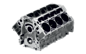
Automotive Manufacturing: In automotive manufacturing, high performance HMCs are used to produce critical components like engine blocks, transmission housings, and suspension parts. With their ability to operate at high spindle speeds and feed rates, they reduce cycle times and enable high-volume production without sacrificing quality. The precision and durability of these machines ensure that complex parts are machined accurately, meeting the industry’s strict performance and safety standards.
Medical Device Manufacturing: High performance HMCs play a crucial role in the medical device industry, where parts such as surgical instruments, orthopaedic implants, and prosthetics need to be produced with extreme accuracy. These machines provide the multi-axis machining and high-speed capabilities needed to create intricate shapes with excellent surface finishes. In this highly regulated field, the tight tolerances and precision offered by high performance HMCs ensure that medical devices meet stringent quality and safety requirements.
Energy Sector: The energy sector, including oil, gas, and power generation, relies on high performance HMCs for the production of robust and large-scale components such as valves, pumps, and turbine parts. These machines can efficiently machine tough materials and complex geometries required in the sector, where components must withstand high pressures and harsh operating environments. High performance HMCs also offer the heavy-duty cutting capabilities necessary to meet the energy industry’s demands for durability and reliability.
Heavy Equipment Manufacturing: In the production of heavy equipment for industries like construction and agriculture, high performance HMCs are used to machine large and complex parts such as frames, gear housings, and structural components. These machines’ ability to handle multi-axis machining of large, tough workpieces ensures that the components meet high standards of durability and precision. The faster machining speeds and improved chip management in high performance HMCs help manufacturers keep up with high production demands while maintaining quality.
Defence and Military Applications: For defence and military manufacturing, high performance HMCs are used to produce precision components for weapons, vehicles, and aerospace defence systems. These parts often need to be machined from high-strength materials and meet strict military specifications. The multi-axis capabilities and high precision of these HMCs allow for the production of complex, mission-critical parts in a timely and efficient manner, ensuring they meet the reliability standards required in defence applications.
General Manufacturing: In general manufacturing, specialised CNC machines, such as high performance HMCs are used to produce a variety of parts and components across multiple industries. Their high-speed machining capabilities and ability to handle complex geometries make them valuable in manufacturing everything from small precision parts to large, multi-sided components. Manufacturers benefit from reduced setup times and faster production cycles, which help streamline operations and improve overall productivity.
Bharat Fritz Werner Ltd. (BFW) is a pioneering name in machine tools, manufacturing solutions, and technological innovation.
Subscribe to get notified about latest events, new products, industry insights and other updates from BFW, directly to your inbox.

Trusted Global Manufacturing Technology Partner
Copyright 2025 © BFW, Managed by Appac Mediatech Pvt Ltd
Are you looking for a product or service offer? Let us know your requirements and we will get back to you soon.
We will get back to you soon
Download our comprehensive product brochure and learn how our products should support your needs.

Kindly complete the form with the required information